
Hypervolt Home 2.0 EV Charger Operating and Installation Manual
Introduction
Thank you for choosing Hypervolt, our team know you will be pleased by how easy it is to install and how amazing the functionality is of your new Home 2.0 Smart EV Charger.
Hypervolt aims to provide customers with state-of-the-art equipment embracing industry leading smart features backed up by excellent customer service.
The Hypervolt Home includes advanced built in automatic monitoring systems for intuitive use and to ensure your safety.
This guide will provide instructions on how to correctly install and operate your new charger; by reading this guide it will ensure you or if you are an installer, your customer receives the best experience when using the charger.
Safety Notice
The installer and end user must read and fully understand the safety instructions provided. Disregard of or actions contrary to the safety information and instructions contained in this document, printed on the device or by other way given may lead to one or all of the following:
- Injury or potential death of the operator, installer and any other third parties.
- Improper operation, function and damage of the charger.
- Damage to the vehicle on charge, building electrical systems and the surrounding environment.
In addition failure to adhere to any of the safety precautions, notices, advice and instructions set out in this guide or by other way given in relation to either the installation or operation of this and all other Hypervolt products will invalidate the warranty.
Legal Notice
This document is intended to be used as a reference guide for the installation and operation of the Hypervolt Home 2.0 EV Charger. The product images shown are for illustration purposes only and may not be an exact representation of the product. Hypervolt Limited reserves the right to make changes to the specifications and processes of the product and documentation at any time and without prior notice.
The Hypervolt Home 2.0 charger has been designed, developed and manufactured to satisfy requirements, safety dispositions and norms in accordance with the directives presented in the declaration of conformity.
Disposal
Important information for the correct disposal of the product in accordance with Directive 2012/19/EC. At the end of its useful life, the product should not be disposed of as urban waste. It must be taken to a collection centre for special and differentiated disposal or to a distributor that provides this service.
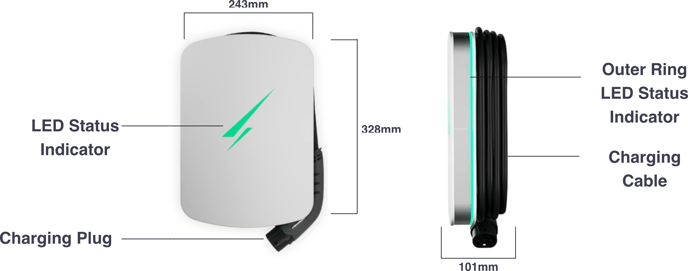
Getting to know your Hypervolt: Product Overview
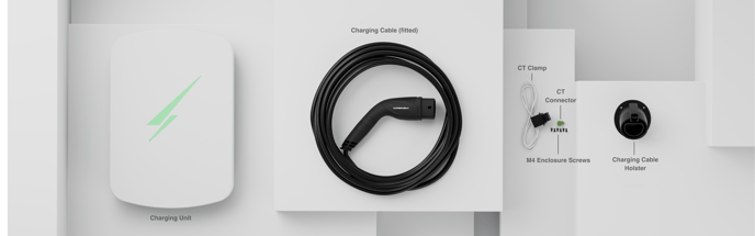
What comes in the box ?
Installation: Getting Started
Please read before starting your install!
- Hypervolt products must be installed by suitably qualified trained personnel only.
- Above all else the Requirements for Electrical Installations as set out in BS7671 (as amended) must be followed with special attention to section 722.
- In addition to the above the guidance given in the “Code of Practice for Electric Vehicle Charging Equipment Installation” (as amended) by the IET must also be followed.
- If you are unsure about any part of the installation of a Hypervolt product you must obtain clarification from our technical department before proceeding.
- After installation and within 48hrs the unit must be registered as having been installed. This is done by scanning the QR code on the side of the unit or online. This is to validate the warranty, failure to do so will void the warranty. Installers should aim to do this before leaving site.
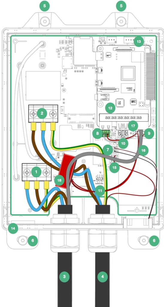
Location of Important Components
- Incoming Supply Connections (up to 10mm²)
- Tethered Cable Connections
- Incoming Supply Cable (HyperConnect)
- Tethered Cable with Plug
- Top Mounting Holes
- Bottom Mounting Holes
- Fan Connection
- CT Connection (Current Clamp)
- RCD Connection
- ALM Adjustment Dial
- Derating DIP Switches
- Raspberry Pi
- LED Front Plate Connection
- Cutout for Additional Cable Gland
- CP Connection
- RJ45 Hardwire Connection
- Ethernet Port
- RCD
Installation: Enclosure Parts
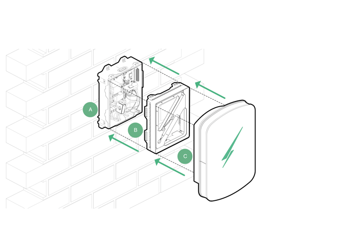
A – Back Box
B – LED Plate
C – Front Enclosure
Installation: Mounting
Before removing the LED Plate (B) we recommend first mounting your Hypervolt charger.
Please note the following;
– The mounting site should be flat, away from extreme external influences and close enough to the EV to prevent the tethered cable causing a trip hazard.
– There are many different fixings that can be used depending on the material being fixed to so please provide the ones most appropriate, no fixings are supplied.
– The unit comes with a cardboard mounting template however a metal version can be purchased.
– Pole Mounts are available for purchase should you opt to install your Hypervolt as a freestanding charger.
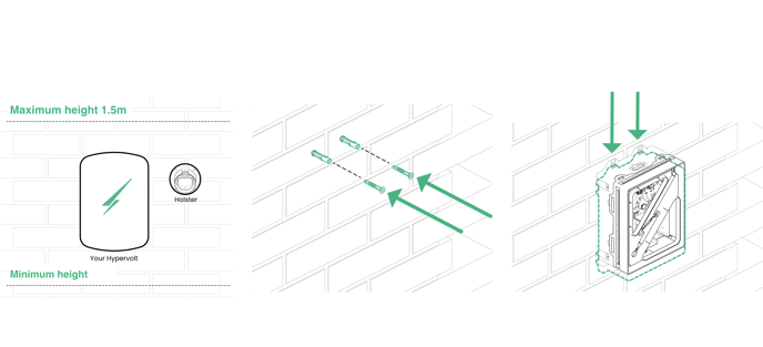
STEP 1
Use the cardboard drilling template supplied with your Hypervolt to mark out the mounting holes for the back box (B).
Your Hypervolt unit and accompanying holster should be fixed between 0.5m and 1.5m above the ground. We recommend the holster position in the diagram is the best place for it relative to the Hypervolt’s position.
Drill out all 4 fixing holes and fit the top 2 screws (5) leaving them 10mm out. For brick the recommended would be to use a 5.5mm SDS drill, Red plugs & 4x40mm screws. Hang the Hypervolt on to the top two screws.
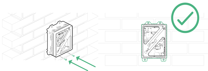
STEP 2
Insert the bottom 2 screws (6) then tighten all 4 up pinching the unit up tight to the wall.
Make sure the unit sits level and adjust if required.
Installation: Accessing the Connections
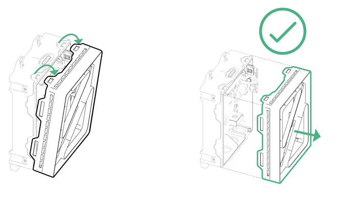
STEP 3
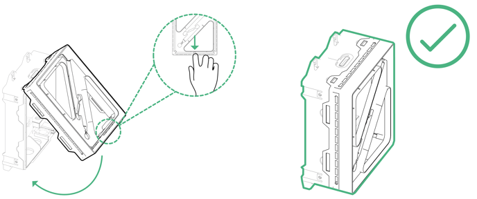
The Hypervolt has a removable LED plate which should be removed to access the connections and then replaced before the front enclosure (C) is fitted.
To remove simply pull up on the top two tabs and unhook the plate.
Separate the square white cable joint behind pressing down on the latch to release it. The unit will be shipped with this connector already disconnected however still take care on first removal just in case.
Put the LED Plate back in the box to keep it save until you refit it.
Installation: Wiring and Connections
The Hypervolt requires two types of connections; one for supplying power and one for sending CT information (Load Management (ALM), Solar Input etc.)
The CT connection can also be used for hardwiring internet if a primary Wi-Fi connection is not available or too weak, please refer to our website on this. Cat5 cable should be used for the CT/Hardwire connection as it contains enough cores for all eventualities. Hypervolt can supply HyperConnect Cable which contains the power & data cable (Cat5) all in one for a neater easier install. Cables should only come in via. the bottom gland positions. Position (14) can be drilled out and a gland fitted to bring in a separate data cable and maintain separation. Separate data & power cables should not be run directly next to each other outside of the unit.
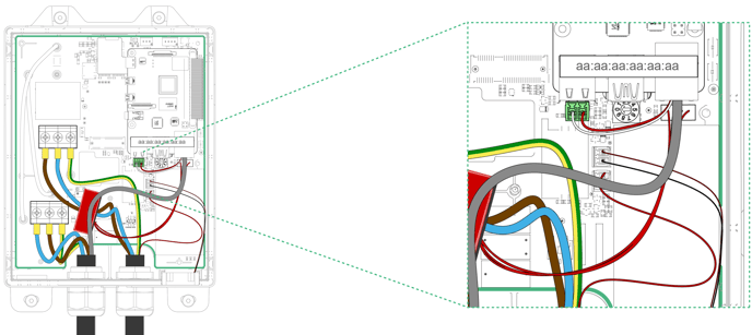
STEP 4
Connect the power cables to the incoming terminals (1) and tighten to 2Nm. We recommend using ferrules on stranded cables. Pictured is HyperConnect (3) cable available from us. Do not use powered screwdrivers to tighten terminals.
Tighten the CTS Gland provided to hold the incoming cable in place. If you are using an SWA cable then the CTS gland should be replaced for an SWA Gland (Not Provided).
STEP 5
Connect the Cat5 cable to the CT green plug (8), use the brown pair keeping the White/Brown cable to the left and the Brown to the right. Remember to joint the White/Brown to the White cable a the CT and the Brown to the Black.
If you need hardwired internet use the remaining Orange and Green pairs terminated in an RJ45 plug which can be inserted in the RJ45 socket (9). More details of this are on our website.
Installation: Power and CT Connection
STEP 6
There are two methods of connecting the Hypervolt to an electrical supply (Connection Method 1 or 2) which can be done using a further two methods of wiring (1 Wire Method or 2 Wire Method).
Connection Method 1:
A separate consumer unit spurred into the existing meter tails is installed just for the use of the Hypervolt unit. HyperConnect (1 Wire Method Orange cable only) is run from the Hypervolt unit and a joint made within the consumer unit to the CT Clamp Cable. If you are not using HyperConnect then run a separate supply cable and separate Cat5 cable for the CT (2 wire method Orange & Black Cables) these cables must not be run directly alongside each other.
Connection Method 2:
This is the same as above apart from the supply is taken from an existing consumer unit. Remember not to share an RCD with another circuit. Both wiring methods can still be used.
For Both Methods
Connect the power cable to a suitably sized protective device. The Hypervolt takes a maximum load just below 32A. Consideration should be given to if a 32A or 40A device is used based upon the operating environment. A 32A device may run too warm and trip out prematurely over a long charging period if it is between other loaded devices. The Hypervolt must be on an individual (not supplying other circuits) A Type RCD double pole device. If an RCD is used an additional MCB (32A or 40A) will need to be included for overload protection. If an A Type RCBO (32A or 40A) is to be used please remember this must also be double pole.
Installation: Refitting the LED Plate
STEP 7
Once you have finished wiring in your Hypervolt charger, you will need to re-fit the LED plate (B). First reconnect the square white LED cable connector back together,
it should click. Put the top two tabs of part (B) over their locators on the top side of the back box (A). Now pull down on the middle bottom edge of part (B) and click
the bottom into place. Take care not to trap any cabling between parts A & B.
Installation: Fitting the Front Enclosure
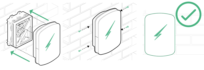
STEP 8
Lastly slide the front enclosure (C) onto the unit and secure using the four M4 screws supplied in the box. A small amount of pressure will be required on the front or the front enclosure to line the holes up. Please take care not to cross thread the screws and certainly do not do these up using a powered tool such as an electric screwdriver. Spare screws and captive square bolts are supplied if you lose or damage one. To change the captive bolts first pop out the green retaining peg.
Installation: Monitoring and Protection Devices
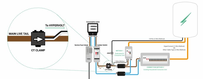
CT (Current Transformer) often called Current Clamp or CT Clamp
The single CT clamp supplied must be fitted to measure the main load on the property and discover solar export.
The CT clamp provided should go around the main incoming Live (Brown or Red) meter tail with the arrow pointing in the normal direction of current flow (Please refer to page 10 for further installation instructions). It is equally important that the wires from the CT clamp go the correct way round inside the Hypervolt unit, the White Wire should go in the LEFT and the Black Wire should go in the RIGHT of the green connection plug (8). If you extend the wires remember to follow these connections through. Details of how to test the CT clamp are on page 15.
The CT Clamp should be positioned where it will measure the total load on the property. If you wish to position it in a different location due to practicality permission should be sort from Hypervolt first. Be aware that positioning other than at the origin of the supply will limit the functionality of the Hypervolt.
Note: The CT clamp wiring can be extended up to 40m using Cat5e cable or 80m using HyperConnect cable.
RCD (Residual Current Device)
An RCD is a safety device used to ensure that the charger stops supplying electricity in the event that there is an electrical fault to earth.
The Hypervolt has built-in 6mA DC protection but no built-in AC protection, it must therefore be connected to an individual “A” Type Double Pole RCD or RCBO not exceeding 30mA; complying with IEC61008-1 /IEC61009-1 / IEC60947-2 / IEC62423.
PEN Fault Protection
Hypervolt chargers have built-in PEN fault protection which means they can be connected to a PME (TN-C-S) incoming service which shares Neutral & Earth in the same conductor. There is no requirement to install an additional earth rod. In the event that the Protective Earth and Neutral (PEN) conductor becomes damaged/disconnected our PEN Fault system will isolate all conductors to protect the user from potential danger a PEN fault presents.
Overheating Sensing
Hypervolt chargers have built-in temperature sensors; in the event where it recognises there is too much heat being generated it will reduce the current being delivered to the EV, this will ensure the charger is not damaged as a result of overheating.
Installation: Automated Load Management
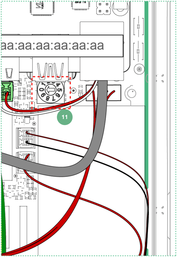
ALM (Automated Load Management) Testing
- Isolate the supply to the Hypervolt & remove the cover.
- Locate the ALM setting dial (10) in the bottom left corner of the PCB (Printed Circuit Board).
- Set the ALM dial to “2”. Take care to set the dial correctly, note that it comes from the factory set to “0”.
- Replace the cover and turn the power back on.
- Plug the Hypervolt into your EV testing adaptor and set the adaptor to “C” (Car Charging), the bolt on the front of the charger will go green.
- Turn on the customers kettle to increase house load to above 10A.
- Watch that the green bolt on the front of the Hypervolt decreases.
- Turn the kettle off and check the green bolt extends back.
- Isolate the supply to the Hypervolt & remove the cover.
- Set the ALM dial (10) back to the required load setting (60A is 6, 80A is 7 & 100A is 8). You might choose to set this to 60A even if the main fuse is 100A.
- Replace the cover and turn the power back on.
ALM will not function if the CT clamp is not fitted.
Top tip: It is a good idea to carry a basic amp measuring clamp meter with you as part of your installer kit. This way you can measure the amperage being drawn by the property to confirm it starts under 10A.
Installation: Maximum Operating Current
It is possible to limit the maximum current the Hypervolt Charger will operate at by permanently derating the unit using the internal dip switches. This is called a “Hard Set” as opposed to a “Soft Set” which can be done from the app.
Setting the Maximum Operating Current (Hard Set)
1. Isolate the supply to the Hypervolt & remove the cover.
2. Locate the “Hard Set” dip switches (11) in the bottom left corner of the PCB.
3. The dip switches are factory set to the maximum 32A.
4. Change the middle and righthand dip switches to your required maximum output as per the following positions:
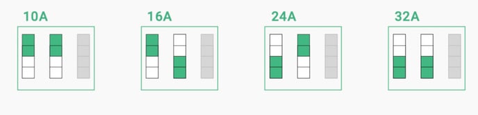
5. Replace the cover and turn the power back on.
Reducing the maximum operating current can sometimes be requested by your DNO and should be done using the Hard Set method only not the soft set.
Do not change the position of the lefthand dip switch which should remain in the down position. The unit comes set to 32A (All dips down).
Using your Charger: Getting Online via the Hotspot
There is a secondary method that you can used to get your Hypervolt Online. We call this the “Hotspot Method”. It’s useful is you are having Bluetooth connection issues or don’t have an account. This is best done on a smart phone.
1. Adjust your settings
If you are connected to a Wi-Fi network temporarily turn off ‘auto connect’ or tap ‘forget the network’ and ensure your mobile data is turned off as well.
Note: Before tapping ‘forget the network’ make sure you have your network password noted so you can reconnect it later.
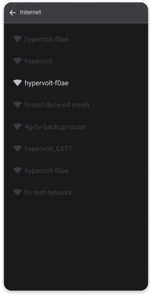
2. Finding the hotspot
Go to your wifi settings and search for a new Wi-Fi network, amongst your list of connections your hotspot should appear as ‘Hypervolt-xxxx’ (note xxxx represents a mixture of numbers and letters).
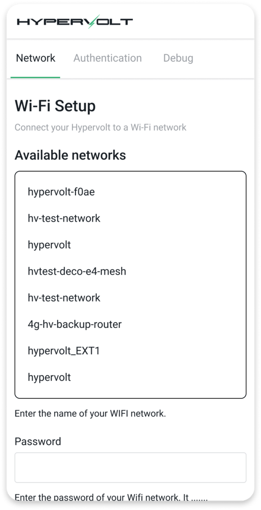
3. Connecting to the hotspot
Next open your browser i.e. Safari or Google Chrome and type in the address bar ‘hypervolt.energy’. When the page loads check you are in the ‘network’ tab.
Alternatively use this IP address: 172.16.73.1

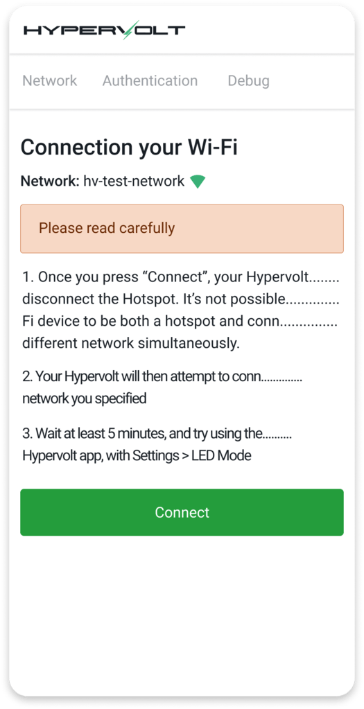
4. Connecting to Wi-Fi
Tap on the Wi-Fi network you want to connect to and fill in the password in the box below.
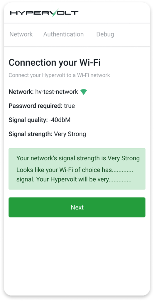
5. Review
Tap ‘next’ and an information page will come up giving you an indication of signal strength. Make a note of this and tap ‘next’. It needs to be better than -70dBm.
6. Confirmation and charger status
You will be presented with the confirmation page, please read through and then tap ‘connect’. The ring around your Hypervolt charger will change from pulsing white to solid blue to confirm connection.
Regulation Changes Notice
Applies to all Hypervoltchargers sold after 30th June 2022
The government commitment that all new cars & vans must be fully zero emissions by 2035 will significantly increase the demand on the electricity system. To help manage this demand “Smart Charging” of Ev’s by “Smart Chargers” has always been encouraged and the new 2021 No 1467 Regulations just enforce some further requirements of “Smart Chargers”. The Hypervolt Home series have always been smart chargers and already complied with most of the changes but here is a bit more information about what’s new:
Note to Installers: Any default settings changed to enable testing of the Hypervolt Unit must be set back to the default setting upon completion of the installation. Setting – Your Hypervolt – Default Schedule and Random Start – Both Set to On.

Default Schedule
Your Hypervolt will come with a pre set off peak schedule. A pop up window will let you know this on the “Select Mode” page. You can opt out by either changing the schedule, choosing Plug & Charge or unselecting “Default Schedule” on the Your Hypervolt page.
Random Start
Your Hypervolt will come pre set to do a random start every time a charging session starts in Boost Mode whether that be from a schedule or a straight Plug & Charge. The charge will start anytime up to 10 minutes. The delay will be shown just below the Hypervolt icon on the start page. The charging indicator will change from “Waiting” to “Charging” when the random delay is over. You can opt out of this by unselecting it on the “Your Hypervolt” page.
