Safety Notice
The installer and end user must read and fully understand the safety instructions provided. Disregarding safety information and instructions contained in this document, printed on the device or by other way given may lead to one or all of the following:
- Injury or potential death of the operator, installer and any other third parties.
- Improper operation, function and damage of the charger.
- Damage to the vehicle on charge, building electrical systems and the surrounding environment.
In addition, failure to adhere to any of the safety precautions, notices, advice and instructions set out in this guide in relation to either the installation or operation of this and all other Hypervolt products will invalidate the warranty.
Legal Notice
This document is intended to be used as a reference guide for the installation and operation of the Hypervolt Home 3 Pro EV Charger. The product images shown are for illustration purposes only and may not be an exact representation of the product. Hypervolt Limited reserves the right to make changes to the specifications and processes of the product and documentation at any time and without prior notice.
The Hypervolt Home 3 Pro charger has been designed, developed and manufactured to satisfy requirements, safety dispositions and norms in accordance with the directives presented in the declaration of conformity.
Disposal
Important information for the correct disposal of the product in accordance with Directive 2012/19/EC. At the end of its useful life, the product should not be disposed of as urban waste. It must be taken to a collection centre for special and differentiated disposal or to a distributor that provides this service.
Getting Started
Please read the entire guide before starting your install - you will need to know how you are cabling the unit and prepare the cable entry points with IP66+ rated glands or grommets.
Hypervolt products must be installed by suitably qualified electricians.
The Requirements for Electrical Installations as set out in BS7671 (as amended) must be followed with special attention to section 722. In addition, the guidelines given in the “Code of Practice for Electric Vehicle Charging Equipment Installation” (as amended) by the IET must also be followed.
If you are unsure about any part of the installation of a Hypervolt product you must obtain clarification from our technical department before proceeding.
After installation and within 48hrs the unit must be registered as having been installed in order to validate the warranty. This is done online, and you must do this before leaving the site. Failure to do this will void the warranty.
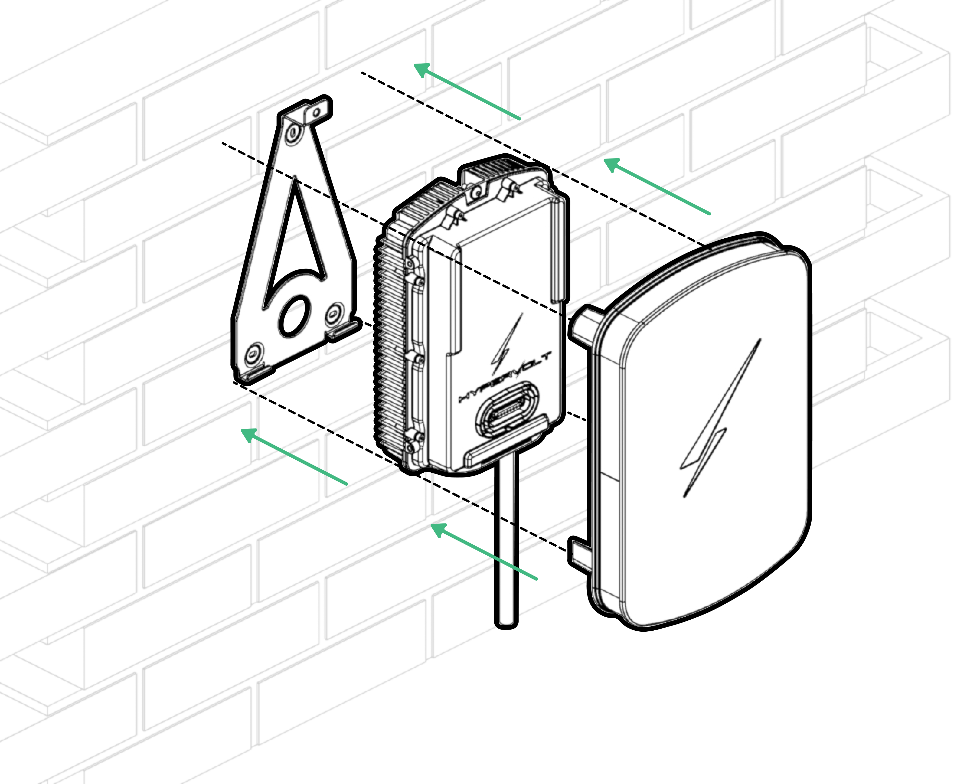
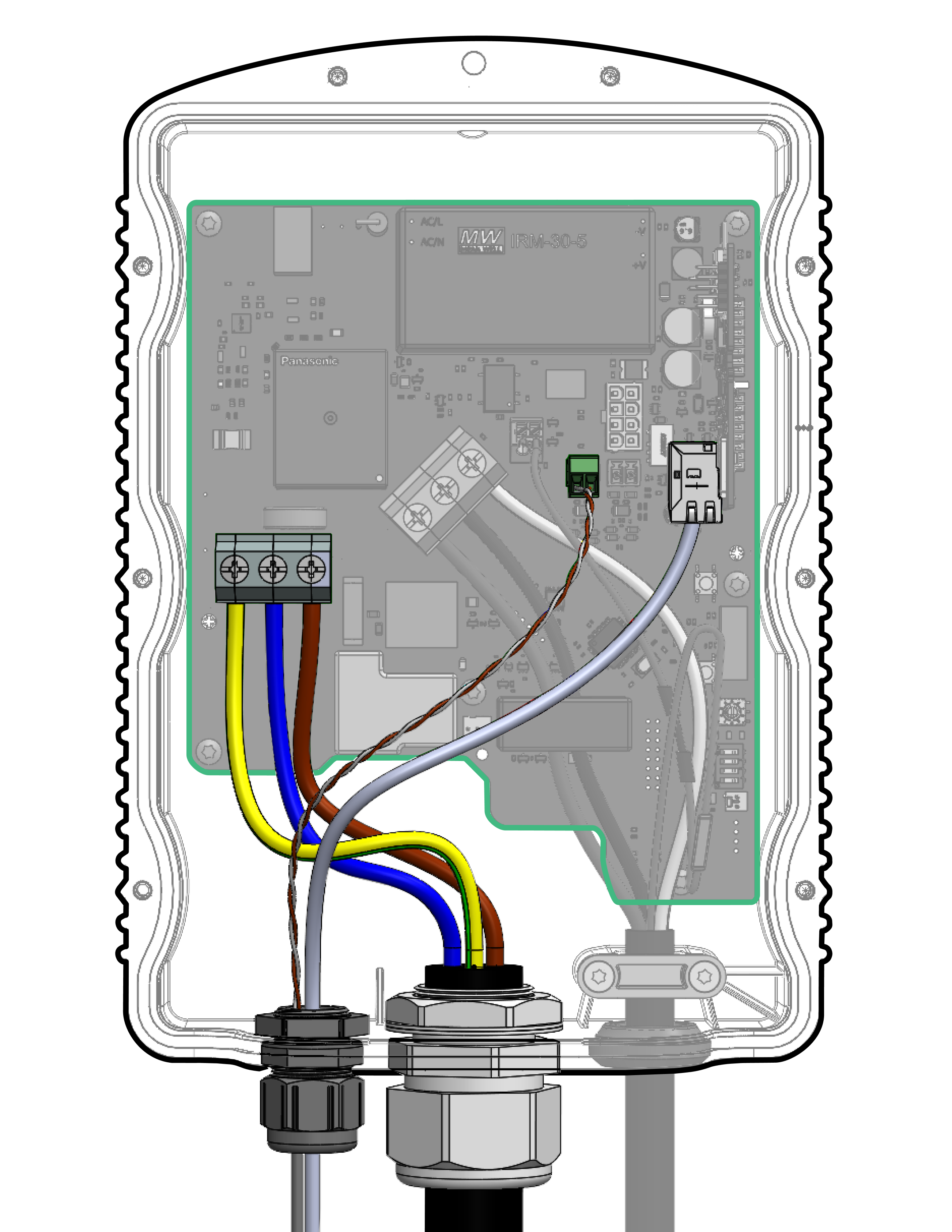
Location of Important Components
- Incoming Supply Connections
- Tethered Cable Connections
- CT1 connector
- CT2 connector
- RJ45 Data Cable Connection
- ALM Adjustment Dial
- Derating Dip Switches
- Sensing Device (RCD-DD)
- LED Front Plate Connection
- Primary Processor Daughtercard
- Rear Cable Entry Cutout
- 32mm Cable Entry Cutout
- 25mm Cable Entry Cutout
- Top Mounting Holes
- Bottom mounting Holes
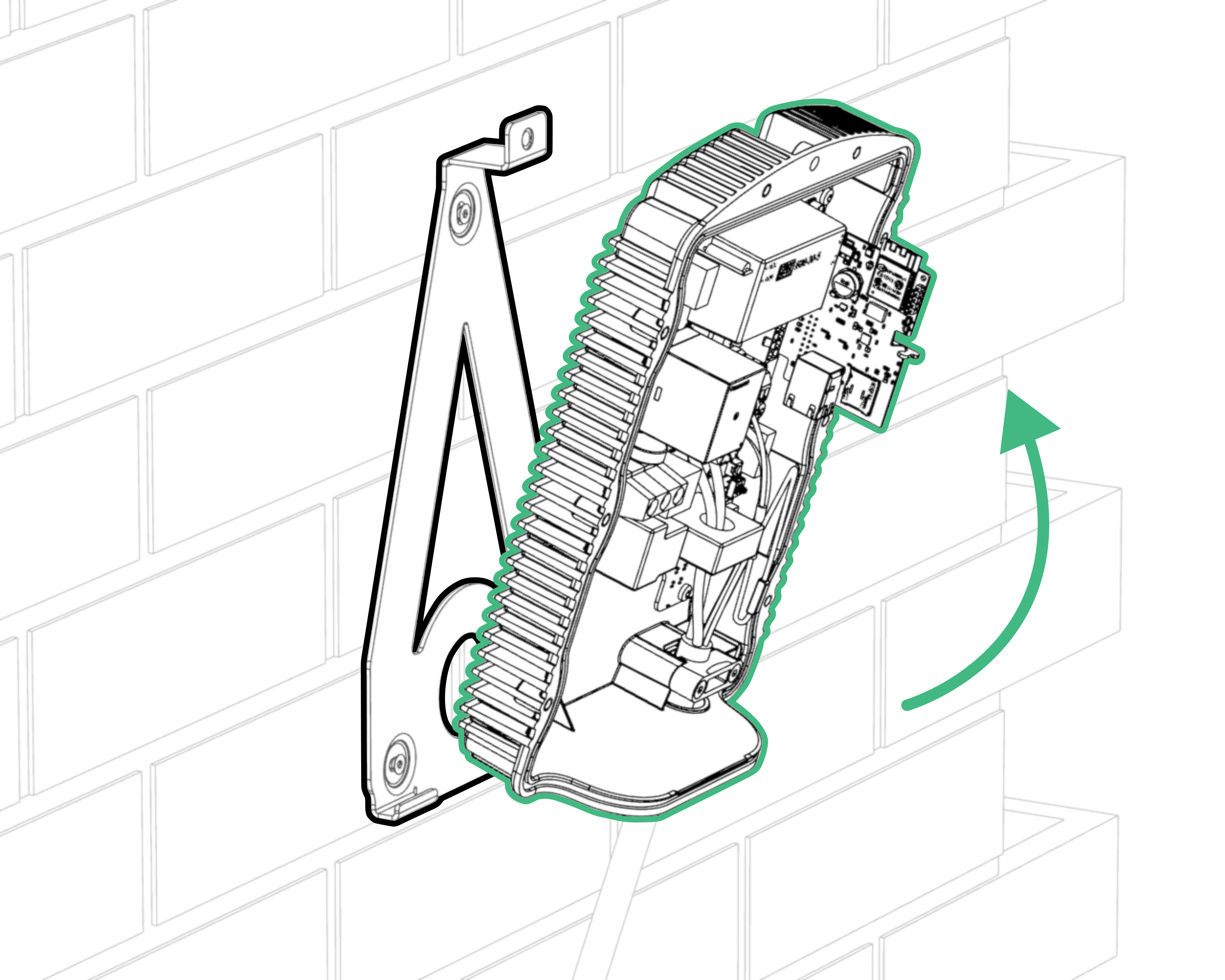
Mounting the Charger
STEP 1
- The installation location should be on a clean flat surface with good WiFi signal (if used) that is protected from the weather.
- Locate the pull tab at the lower part of the box. Remove this from the box to reveal the metal wall bracket.
- Use the cardboard drilling template to mark the mounting holes for the wall bracket and holster.

- Your Hypervolt unit and accompanying holster should be fixed between 0.5m and 1.5m above the ground. See the above diagram for the recommended placement.
- Drill out all 3 fixing holes for the bracket, then fit the top screw leaving it ≈10mm out. Then fit the bottom 2 screws and adjust as needed for leveling.
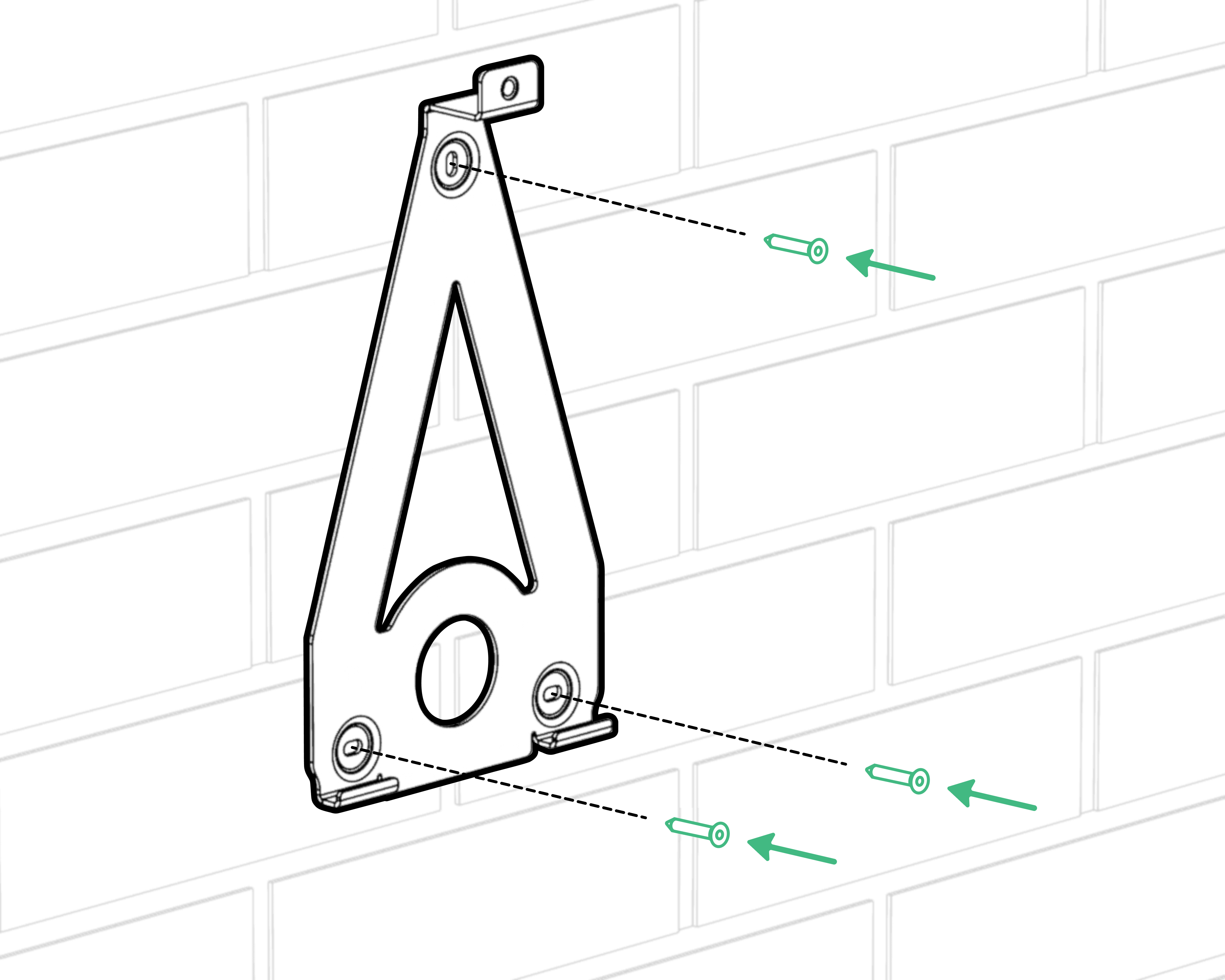
We recommend using a minimum 5mm non-countersunk head to secure the mounting bracket. Please choose the depth and plugs based on the material where you’re installing the unit.
STEP 2

Insert the bottom screws then tighten all 3 up; we recommend using a spirit level on the top of the bracket.
STEP 3
Now that you have placed the mounting bracket, you should mount the cable holster. We recommend placing the holster approximately half a meter to the side, measured from the center of the mounting bracket.
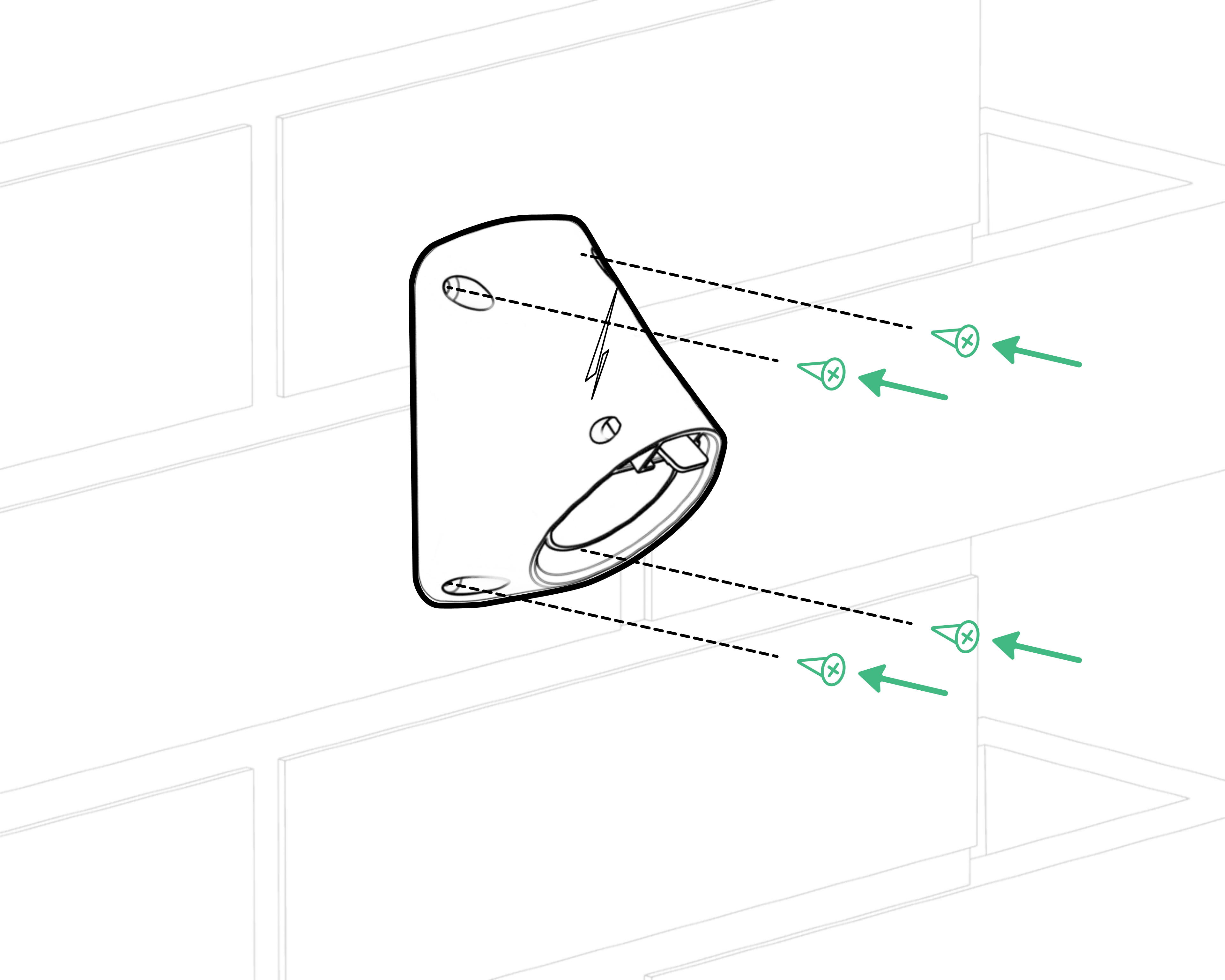
You should use a screw with a 5mm countersunk head to secure the holster. Please choose the depth and plugs based on the material where you’re installing the unit.
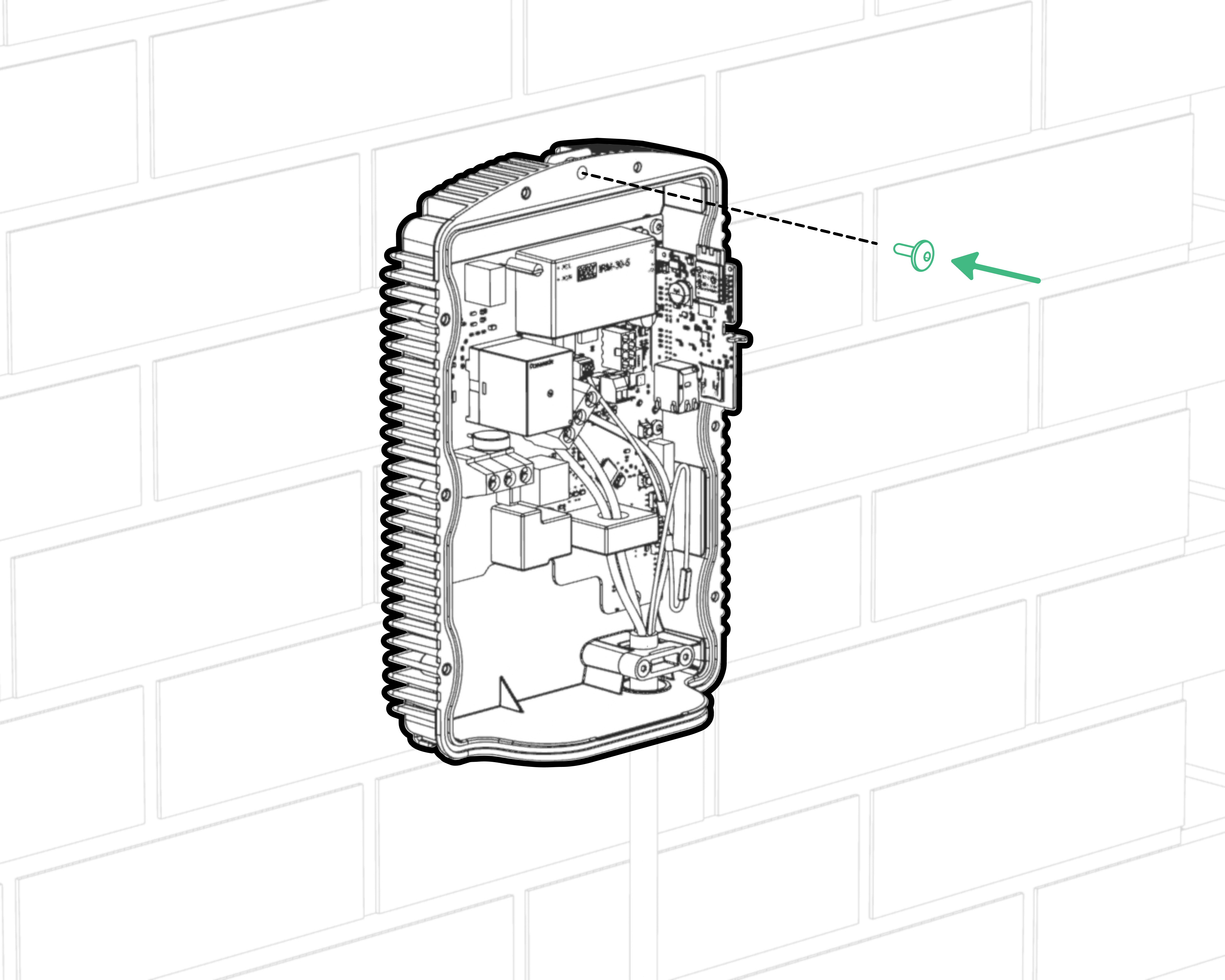
STEP 4
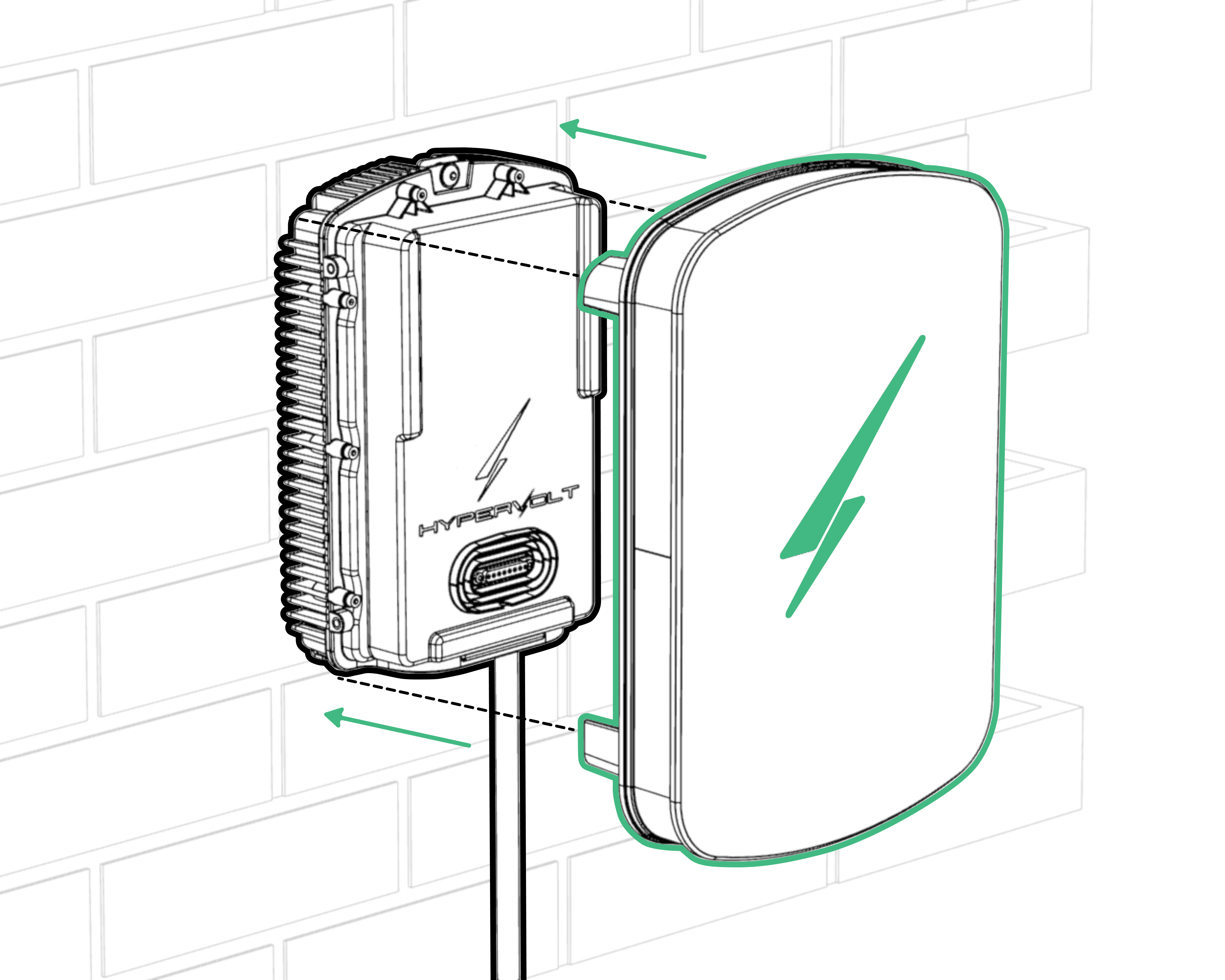
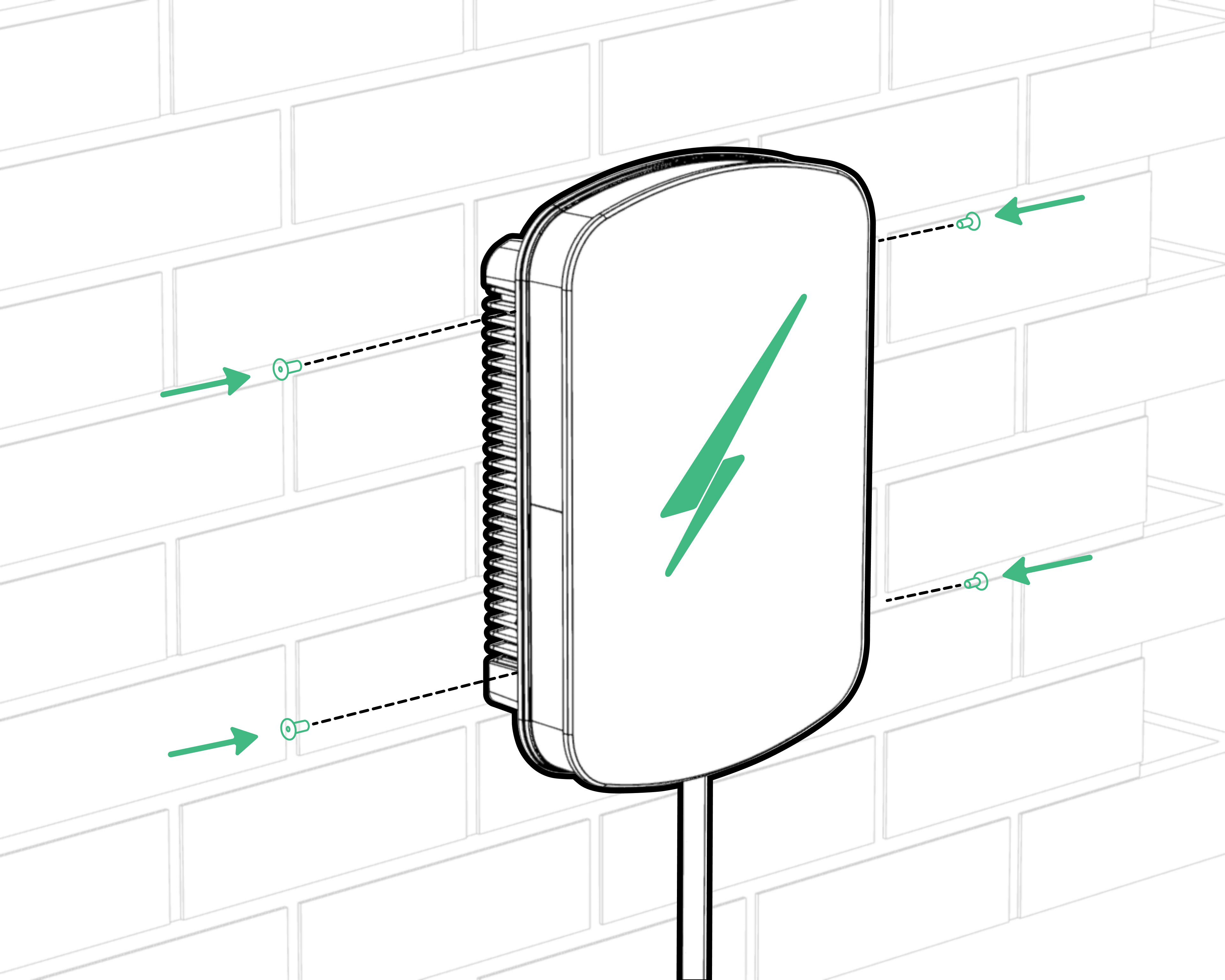
- You will need to remove the rear enclosure lid to install the cabling and set ALM and current limit appropriately on the hardware.
- Put both components, and the provided screws, safely to one side.
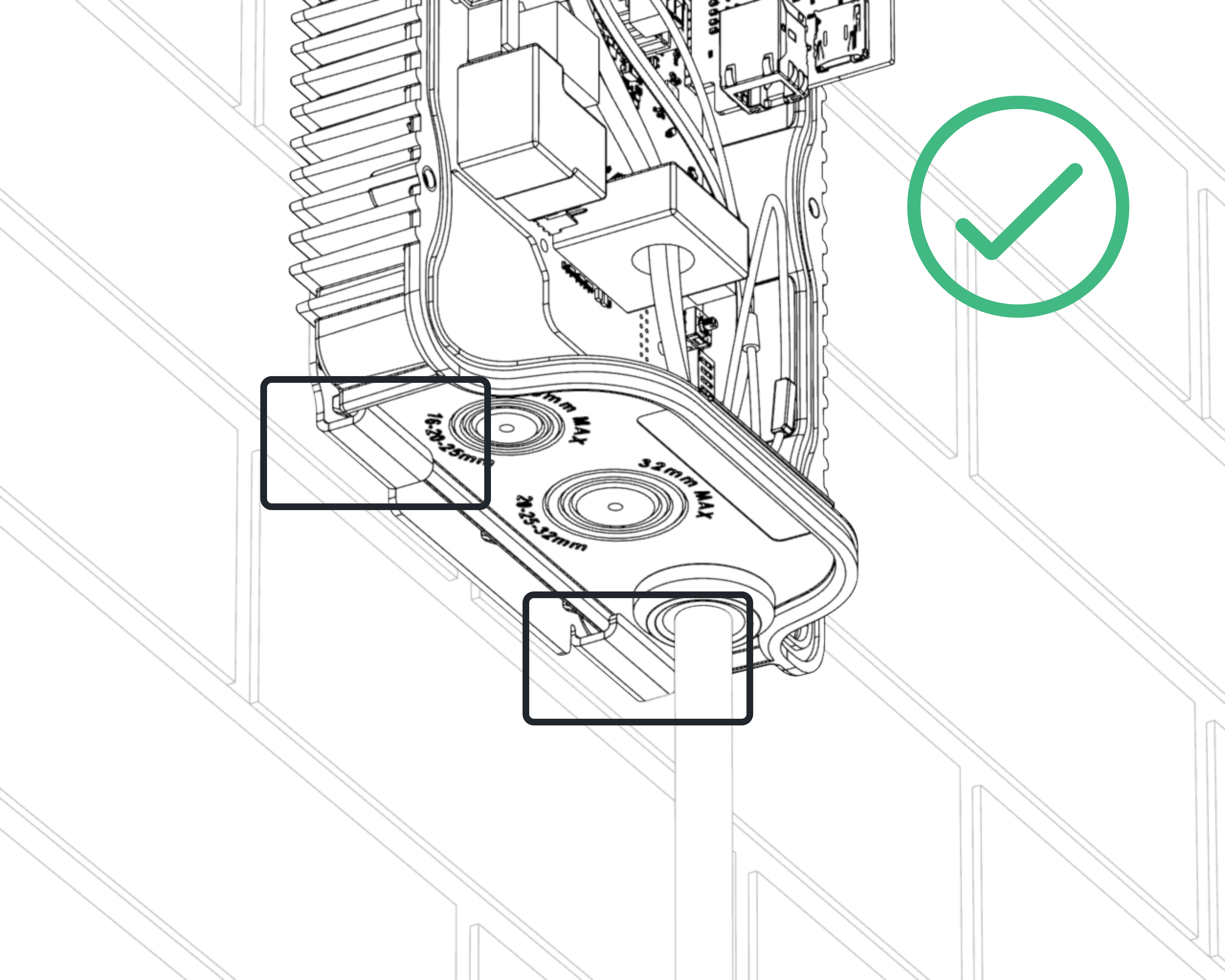
- Before you mount the unit to the wall, you should also drill out the cable entry point(s) that you will use for the installation.
STEP 5
Use the supplied M6 x 16mm screw for the top central hole to secure the charger to the wall bracket.
Cable Installation
The Hypervolt requires two types of connections: one for supplying electricity and one for sending CT information (Load Management, Solar Input etc.). A hardwired ethernet connection for internet is optional but recommended as this does not suffer from atmospheric changes & stability issues sometimes seen with WiFi.
Be sure the method you use to supply electricity to the Hypervolt charger is compliant with the BS7671 Wiring Regulations, particular attention should be given to section 722. Remember external RCDs must be as a minimum Type “A”, individual and double pole (Including RCBOs). SPDs should be fitted with consideration given to whether a type 1 or type 2 device would be more suitable.
Select the size of your incoming cable depending on your protective device rating (see next page), installation method and calculated voltage drop. Ensure that the cable size used to supply the Hypervolt is as generous as possible, we recommend 10mm or greater diameter cable especially on longer runs. This will prevent unwanted losses in the cabling and ensure the sensitive energy measurements are given the best quality signal in order to allow for more accurate home energy usage calculations.
All holes must be suitably sealed to prevent water ingress. The warranty is voided if the IP rating of the unit is not maintained or installations are not compliant with BS7671.
We have three recommended options for cable installation, as follows:
OPTION 1

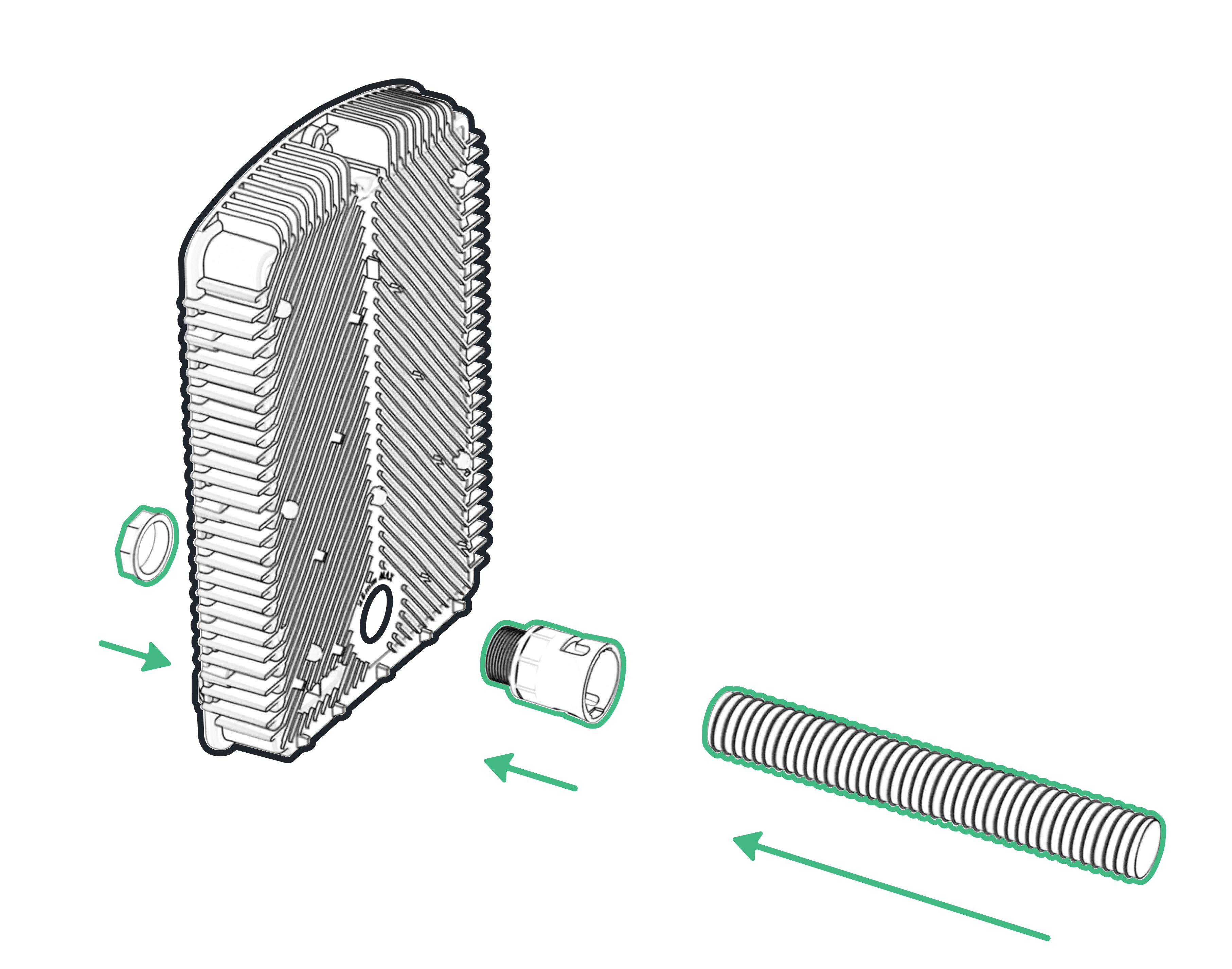
Rear entry, through an Al28/M25/A/GR Straight Adaptlok Fitting with PVC Conduit 28mm OD maximum for multiple cables or a Wiska CLIXX M25 Cable Membrane if using a HyperConnect, EV-Ultra, or other combined cable - see below for the conduit installation side view
OPTION 2

Bottom entry, through the 32mm hole on the base of the charger
OPTION 3
Bottom entry, through both the 32mm hole (for power) and 24mm hole (for data)
All holes should be suitably sealed to prevent water ingress. The warranty is voided if the IP rating of the unit is not maintained or installations are not compliant with BS7671.
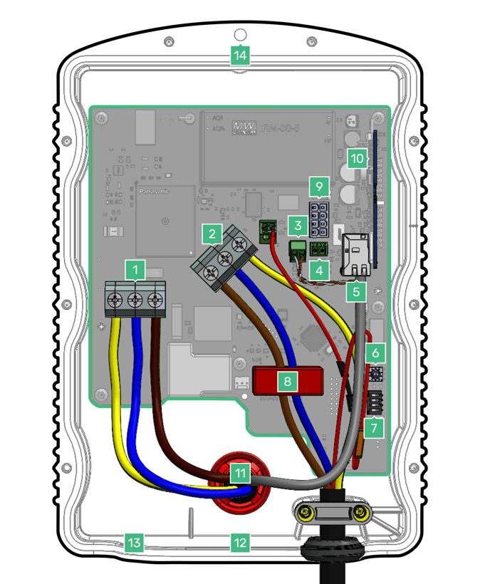
Wiring
STEP 1 (At the Hypervolt)
- Connect the electrical supply cable to the terminals (1) and tighten to 1.8Nm. We recommend using ferrules on stranded cables. Do not use powered screwdrivers on the terminals.
- Tighten the CTS gland to hold the incoming cable in place. If you are using an SWA cable then the CTS gland should be replaced for an SWA Gland.
STEP 2 (At the Hypervolt)

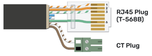
Connect the CT clamp supplied to the green CT plug (4), you can use a/the Cat5 (brown or blue pair) cable to extend the connection but always end up with the white wire in the left of the plug and the black wire in the right (as per colour coding). Use the left plug socket only, as this is for the primary CT.
If you need hardwired internet you can use the remaining Orange and Green pairs terminated in an RJ45 plug following the T-568B wiring standard. This can be inserted into the RJ45 data cable port inside the device (5).
Mains and CT Connection
STEP 1 (At the Consumer Unit)
For Both Methods
A suitably sized overcurrent protective device must be installed to protect the Hypervolt circuit. The Hypervolt takes a maximum load just below 32A. Consideration should be given to if a 32A or 40A device is used based upon the operating environment. A 32A device may run too warm and trip out prematurely over a long charging period especially if it is between other loaded devices. In all cases the Hypervolt must also be protected by an external RCD device (Type AC devices must not be used).

Connect the supply cable. We recommend using method 1 below as this is the easiest way to be compliant.
Connection Method 1:
A separate consumer unit spurred into the existing meter tails is installed just for the use of the Hypervolt unit. HyperConnect (1 Wire Method Orange cable only) is run from the Hypervolt unit and a joint made within the consumer unit to the CT Clamp. If you are not using HyperConnect then run a separate supply cable and separate Cat5 cable for the CT (2 wire method Orange & Black Cables) these cables must not be run directly alongside each other.
Connection Method 2:
This is the same as above apart from the supply is taken from an existing consumer unit. Both wiring methods can still be used.
Fitting the Faceplate
STEP 1
- Reconnect the LED Connector into LED Socket ( )
- Carefully re-attach the rear lid to the unit, making sure to hand-tighten all eight screws.

STEP 2
- Slide the front cover (C) over parts A & B and secure using the four M5x12 countersunk screws supplied. A small amount of pressure will be required on the front to compress the seal and line the holes up.
- Please take care to hand-tighten the screws, rather than using a powered screwdriver, to avoid cross threading the screws.
The wall unit doubles as a cable holder when the charger is not in use. Simply wind the cable around the recess of the unit clicking the charging plug into the holster only once the cable has been wound to prevent twisting.
Monitoring and Protection Devices
CT (Current Transformer)
For general use a single CT clamp must be fitted at the service origin to measure the main load on the property and discover any solar export.
The CT clamp provided should go around the main incoming Live (Brown or Red) meter tail with the arrow pointing in the normal direction of current flow (Please refer to the picture on page 11).
The CT clamp wiring can be extended up to 50m using Cat5e cable or 100m using HyperConnect or EV-Ultra cable.
PEN Fault Protection
Hypervolt chargers have built-in PEN fault protection which means they can be connected to a PME (TN-C-S) incoming service which shares Neutral & Earth in the same conductor. There is no requirement to install an additional earth rod. In the event that the Protective Earth and Neutral (PEN) conductor becomes damaged/disconnected the Hypervolt PEN Fault system will isolate all conductors to protect the user from the potential danger a PEN fault presents.
Overheating Sensing
Hypervolt chargers have built-in temperature sensors; in the event where it recognises there is too much heat being generated it will reduce the current being delivered to the EV, this will ensure the charger is not damaged.
ALM (Automatic Load Management)
For the ALM system to work correctly it is very important that the CT Clamp has been correctly installed
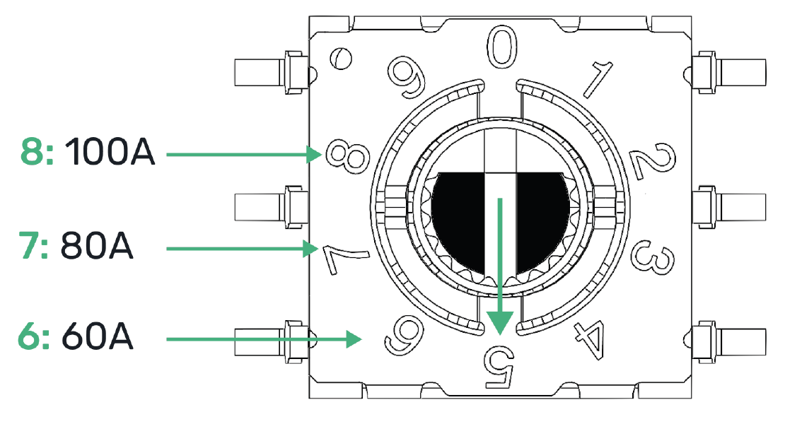
Hypervolt's Automatic Load Management control is used to safely adjust the maximum charging current an EV can take to prevent the charging device being responsible for overloading the electrical service to a property.
When activated the charging current will drop to as low as 6A. Generally the ALM system will activate for short periods every so often. If the ALM is being triggered very regularly this could be a sign that the electrical service to the property is inadequate for requirements.
The dial (6) can be adjusted to set the limit at which the load manager activates. The diagram to the right shows what part of the dial is the pointer, in this case pointing to position 5.
The ALM dial is most normally set to 6 for 60A even in cases where the main fuse value is higher. The units will normally come factory set to position 6, but always check.
Maximum Operating Current
It is possible to limit the maximum operating current for the Hypervolt Home 3 Pro by permanently derating the unit using the internal dip switches. This is called a “Hard Set” as opposed to a “Soft Set” which can be done from the Hypervolt App.
Setting the Maximum Operating Current (Hard Set)
Locate the “Hard Set” dip switches (7) in the bottom left corner of the PCB. The dip switches are factory set to the maximum 32A (all off). Change the first two dip switches (1&2) to your required maximum output as per the following positions:
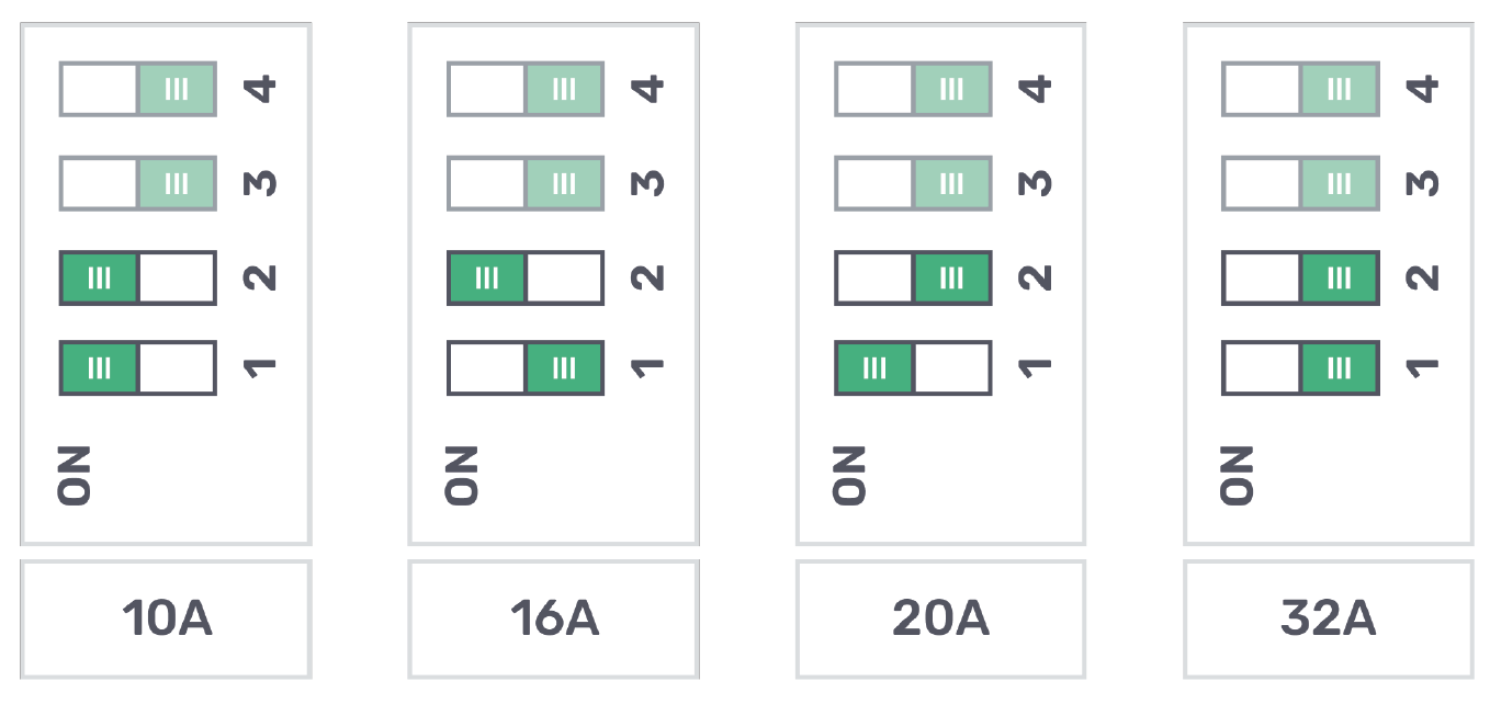
Reducing the maximum operating current can sometimes be requested by a DNO and should be done using the Hard Set method only.
Handover to customer
We recommend using the Hypervolt Installer App, available in both Apple App Store and Google Play Store, to run automated tests and hand-off the newly-installed Hypervolt unit to the customer. The app will guide you through the end to end process, but to summarize:
- Stand near the charger to adopt it using Bluetooth
- Configure the charger to connect to the owner’s home network
- Input the client details (name and email address)
- Run the automated tests from the app to validate that everything is working properly
- After testing is complete, you can mark the installation as complete and automatically hand off to the customer.
If you are not using the app, you will need to manually test the functionality of the charger before confirming that the installation is successful.
Do not remove the lower sticker on the unit - these details will be needed by the owner in the future.