
Information about the HyperConnect charging point installation cable including CT/Ethernet wiring
About the Cable
HyperConnect is Hypervolts own charging point installation cable and available exclusively to installers of Hypervolt products.
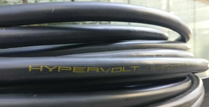
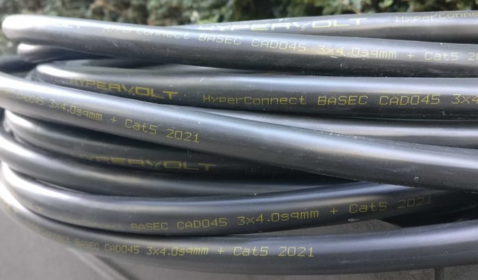
HyperConnect is available as a 4mm CSA 3 core cable in both SWA and non-SWA formats. It is an excellent choice for the installation of Hypervolt Car Charging Units giving a one stop connection solution allowing power, Data and CT connections to be performed from the one same cable.
The Non SWA version is suitable for all internal and external works covering 90% of all installs with the SWA version only being required if there is a need to go underground.
The cable can carry an impressive amount of current and is highly flexible for easy installation. You can supply a single Hypervolt Home 2.0 over a distance of 30m using the Clipped Direct method of installation.
HyperConnect is BASEC (British Approvals Service for Cables) approved.
Connecting the CT & Ethernet Cables
With HyperConnect Cable it is possible to wire the CT Clamp & Ethernet at the same time using the same cable.
The Theory
- RJ45 plugs are wired to standard T568B and this is the colour coding you should use.
- For Ethernet you only need the Orange & Green pairs of the Cat5e cable.
- The Brown pair can be used for the CT Clamp leaving the Blue pair spare.
Terminating the Cable
- Carefully insert the wires into the RJ45 plug starting with White/Orange in the following order:
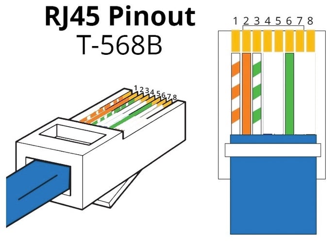
- White/Orange Pin 1
- Orange/White Pin 2
- White/Green Pin 3
- Leave Empty Pin 4
- Leave Empty Pin 5
- Green/White Pin 6
- Leave Empty Pin 7
- Leave Empty Pin 8
- Do this connection at both ends of the cable. You might find it helpful to put the Blue pair in Pins 4 & 5 to help with getting the Green/White wire in the correct hole.
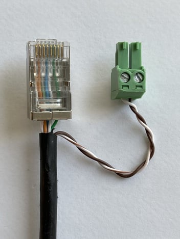
- The Brown pair can now be joined to the CT at the incoming supply end (White/Brown to White & Brown/White to Black). Be careful with your joining method not to break the delicate Cat5e wires.
- Connect the other end of the Brown pairs into the green CT plug with the White/Brown on the Left & Brown/White on the Right.
Always use a network tester to check that the RJ45 plugs are wired in the correct order, never chance it as crossed connections can cause damage.

Cable Specification (240v)
General:
- Conductor (Supply): Copper (Plain Annealed) Class2 Stranded BS EN60228
- Conductor (Data): Cat5e FTP 4 pair Screened
- Insulation: Thermosetting XLPE BS 7655-1.3
- Resistance: 3.08ohms/km @20°C
- Armour (SWA Only): Galvanised steel wire;
- Gland Size (SWA Only): BW20 (Inside) or CW20 (Outside)
- Max. Operating Temperature: 90℃
- Min. Operating Temperature: -15℃
- Min. Bending Radius: 8 x ⌀
- Core Colours: Brown / Blue / Green & Yellow
4mm:
- Resistance: 4.61ohms/km @20°C
- Max. Current Rating Clipped (SWA): 49A
- Max. Current Rating Clipped (Non-SWA): 45A
- Outside Diameter (SWA): 17mm (C7 Cleat)
- Outside Diameter (Non SWA): 15mm (C6 Cleat)
- Volt Drop: 12 mV/A/m
6mm
- Resistance: 3.08ohms/km @20°C
- Max. Current Rating Clipped (SWA): 62A
- Max. Current Rating Clipped (Non-SWA): 58A
- Outside Diameter (SWA): 19mm (C8 Cleat)
- Outside Diameter (Non SWA): 16.4mm (C7 Cleat)
- Volt Drop: 7.9 mV/A/m